DC-DC RELAYS mosfet based
Applications of DC Panel mount Solid State Relay:
- Packaging
- Heat tracing
- Solder wave re-flow systems
- Plastics Industry
- Textile Industry
- Furnace Control
- Excellent functionality
- Robust design
- Longer service life
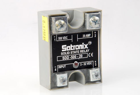
- MOSFET based Optically Isolated
- Load current range: 10, 20, 40 and
- Load voltage upto 60/100/200/400/600 VDC
- Fast switching response
- Normally open type
Note:
- Low voltage disconnect series available for 12 / 24VDC Battery systems
- Load current 60,80, 100 @ 60 VDC available
- High voltage, high current SSR based on MosFET/ IGBT Technology available
- CUSTOM-BUILT models too available
Input Specifications
| Type | SDD – 100 /200/330/600 – 10 | SDD –100 /200/330/600– 20 | SDD –100 /200/330/600– 40 |
| Control Voltage range | 3.5 – 32 VDC | 3.5 – 32 VDC | 3.5 – 32 VDC |
| Input [email protected] | 7.8 mA | 7.8 mA | 7.8 mA |
| Input Current @32 V | 10.6 mA | 10.6 mA | 10.6 mA |
| Input Impedance | Current regulator | Current regulator | Current regulator |
Product Selection eg:
- SDD-100-10 Load voltage : 5-100 VDC
- SDD-200-10 Load voltage : 5- 200 VDC
- SDD-330-10 Load voltage : 5- 330 VDC
- SDD-600-10 Load voltage : 5- 600 VDC
Output Specifications
| Operating Range Amps | 10 | 20 | 30 | 40 | 10 | 20 | 30 | 40 | 10 | 20 | 30 | 40 |
| Voltage Range | 5-100 | 5-100 | 5-100 | 5-200 | 5-200 | 5-200 | 5-400 | 5-400 | 5-400 | 5-600 | 5-600 | 5-600 |
| Max Load current Amps | 10 | 20 | 40 | 10 | 20 | 40 | 10 | 20 | 40 | 10 | 20 | 40 |
| Pulse Drain current | 28A | 42A | 106A | 28 | 42 | 106 | 17 | 36 | - | - | 19 | 39 |
| On-state voltage drop (VTM) | 2.0 | 1.6 | 2.1 | 2.1 | 2.0 | 2.1 | 4.2 | 4.2 | 4.2 | 5.5 | 5.5 | 5.7 |
| Off-state Leakage current @ rated voltage (IDRM) | 0.1 | 0.2 | 0.3 | 0.1 | 0.2 | 0.3 | 0.3 | 0.3 | 0.3 | 0.2 | 0.3 | 0.3 |
| Max. On state Resistance RDS-ON Ω | 0.13 | 0.12 | 0.05 | 0.29 | 0.23 | 0.05 | 0.6 | 0.35 | 0.05 | 0.8 | 0.55 | 0.05 |
| Max Turn on time (μsecs) | 600 | 600 | 600 | 600 | 600 | 600 | 600 | 600 | 600 | 600 | 600 | 600 |
| Max Turn off time (msec) | 1.0 | 1.0 | 1.0 | 1.0 | 1.0 | 1.0 | 1.0 | 1.0 | 1.0 | 1.0 | 1.0 | 1.0 |
General Specifications
| Type | SDD –100/200/330/400/600– 10 | SDD – 100/200/330/400/600– 20 | SDD – 100/200/330/400/600 – 40 |
| Dielectric strength | Min. 2500 VACrms | Min. 2500 VACrms | Min. 2500 VACrms |
| Galvanic separation (I/P to O/P , I/P to case, O/P to case) | 4000 VAC rms | 4000 VAC rms | 4000 VAC rms | Operating temp. | – 40°C to +80°C | – 40°C to +80°C | – 40°C to +80°C |
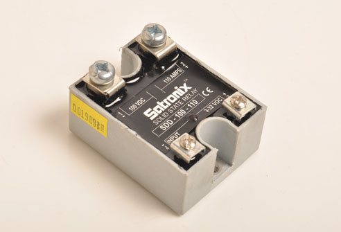
DC-DC High Current
- Load current range: 60,80,100
- MOSFET based Optically Isolated
- Load voltage upto 60 VDC
- Fast switching response
- Normally open type
Note:
- Low voltage disconnect series available O/P:40-100A at 3-75 VDC for 12 / 24VDC Battery systems
- High voltage, high current SSR based on mosFET / IGBT Technology available
- CUSTOM-BUILT models too available
Input Specifications & Product Selection
| Type | SDD –60 – 60 | SDD –60– 80 | SDD –60-100 |
| Control Voltage range | 3.5 – 32 VDC | 3.5 – 32 VDC | 3.5 – 32 VDC |
| Input [email protected] | 7.8 mA | 7.8 mA | 7.8 mA |
| Input Current @32 V | 10.6 mA | 10.6 mA | 10.6 mA |
| Input Impedance | Current regulator | Current regulator | Current regulator |
Output Specifications
| Type | SDD –60 – 60 | SDD –60 – 80 | SDD –60 – 100 |
| Voltage Range | 5- 60 VDC | 5- 60 VDC | 5- 60 VDC |
| Current Range with suitable heat sink(IT) @ 20Amp | 60A | 80A | 100A |
| Pulse Drain current Adc (10msec) | 180 | 220 | 270 |
| Voltage Drop @ Current – VTM | 0.6 | 0.7 | 0.5 |
| Max. On state Resistance RDS-ON Ω | 0.01 | 0.08 | 0.05 |
| Off-state leakage current @ voltage -IDRM | 0.1 | 0.2 | 0.3 |
| Turn-on (max) – T-on | 300 μsecs | 300 μsecs | 300 μsecs |
| Turn-off(max) – T-on | 1.0 ms | 1.0 ms | 1.0 ms |
General Specifications
| Type | SDD – 60 – 60 | SDD – 60 – 80 | SDD – 60 – 100 |
| Dielectric strength | Min. 2500 VACrms | Min. 2500 VACrms | Min. 2500 VACrms |
| Galvanic separation (I/P to O/P , I/P to case, O/P to case) | 4000 VAC rms | 4000 VAC rms | 4000 VAC rms | Operating temp. | – 40°C to +80°C | – 40°C to +80°C | – 40°C to +80°C |
SDD - 1200- 25/40 SERIES
- Load current 25 & 40 A @1200 VDC
- Load voltage 1200 VDC
- Isolation voltage 2500 VRMS
- Fast switching response
- Normal Open Type
- Chassis mounting /Panel Mount Switches
- High voltage SSR based on IGBT Technology
- LED Indicator showing relay ON status
- In-built free wheeling diode across power device
Input Specifications
| Description | Suffix- 12 | Suffix- 24 |
| Control Voltage range | 12 VDC | 24 VDC |
| Nominal Control Voltage Range | 8-16 VDC | 20-28 VDC |
| Minimum Turn-On voltage | 8 VDC | 20 VDC |
| Minimum Turn-Off Voltage | 1.0VDC | 1.0VDC |
| Input Current at Nominal Voltage | 15mA | 15mA |
| Turn-On Time (msec) | 1.5 | 1.5 |
| Turn-Off Time (msec) | 1.5 | 1.5 |
*For Input Control voltage 3-32VDC NO Suffix
Output Specifications
| Type | 25 Amps SDD-1200-25- 12/24 | 40 Amps SDD-1200-40- 12/24 |
| Operating Voltage | 0 - 1200 VDC | 0 - 1200 VDC |
| Max. Transient Over voltage VPK | 1200 | 1200 |
| Max. Off State Leakage Current @ rated voltage | 0.3mA | 0.3mA |
| Max. Load Current | 25 Adc | 40 Adc |
| Min. Load Current | 20 mA | 20 mA |
| Max surge current Adc 10ms | 75 Adc | 120 Adc |
| Operating Voltage | 0 - 1200 VDC | 0 - 1200 VDC |
| Max. On- state Voltage Drop @ Rated current (VDC) | 1.6 | 1.6 |
| Thermal Resistance Junction to Case | 0.4 °C/W | 0.4 °C/W |
| Collector to Emitter IC = 25A VGE = 15V Saturation Voltage TC = 125 °C | 2.15 V | 2.9 V |
General Specifications
| Dielectric Strength Input/ Output/ Base | 2500 VRMS |
| Min Insulation Resistance | 10 9 Ohm |
| Max. Capacitance Input/ Output | 50pf |
| Ambient Operating Temperature range | -30 to 80°C |
| Ambient Storage Temp range | - 40 to 125 °C |
| Encapsulation | thermally conductive Epoxy |
| Weight | 100 gms |
All parameters at 25°C unless otherwise specified In-built freewheeling diode across the power device.
Note: Inductive loads should be diode suppressed. All loads are inductive even ones that are not so labeled. When turned off an inductive load will produce harmful transient voltages. The more perfect the switch the larger the transient voltages. The IGBT output is so nearly an ideal switch that the transient voltages produced by seemingly 'non-inductive 'loads can cause damage if not suppressed. Diodes should be fast recovery type with PIV rated greater than supply voltage.
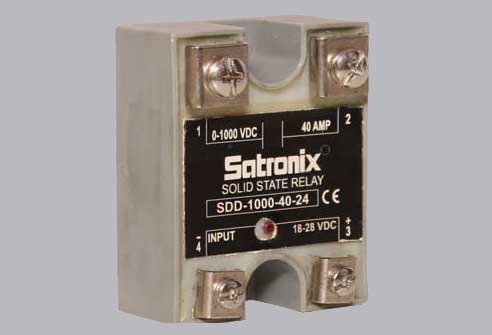
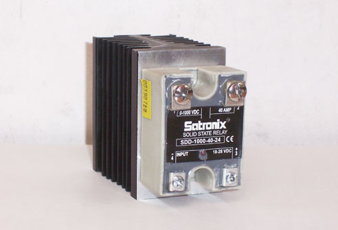
SDD - 1000- 25/40 SERIES
- Load current 25 & 40 A @1200 VDC
- Load voltage 1000 VDC
- Isolation voltage 2500 VRMS
- Fast switching response
- Normal Open Type
- Chassis mounting /Panel Mount Switches
- High voltage SSR based on IGBT Technology
- LED Indicator showing relay ON status
- In-built free wheeling diode across power device
Input Specifications
| Description | Suffix- 12 | Suffix- 24 |
| Control Voltage range | 12 VDC | 24 VDC |
| Nominal Control Voltage Range | 8-16 VDC | 20-28 VDC |
| Minimum Turn-On voltage | 8 VDC | 20 VDC |
| Minimum Turn-Off Voltage | 1.0VDC | 1.0VDC |
| Input Current at Nominal Voltage | 15mA | 15mA |
| Turn-On Time (msec) | 1.5 | 1.5 |
| Turn-Off Time (msec) | 1.5 | 1.5 |
Output Specifications
| Type | 25 Amps SDD-1000-25- 12/24 | 40 Amps SDD-1000-40- 12/24 |
| Operating Voltage | 0 - 1000 VDC | 0 - 1000 VDC |
| Max. Transient Over voltage VPK | 1200 | 1200 |
| Max. Off State Leakage Current @ rated voltage | 0.3mA | 0.3mA |
| Max. Load Current | 25 Adc | 40 Adc |
| Min. Load Current | 20 mA | 20 mA |
| Max surge current Adc 10ms | 75 Adc | 120 Adc |
| Max. On- state Voltage Drop @ Rated current (VDC) | 1.6 | 1.6 |
| Thermal Resistance Junction to Case | 0.4 °C/W | 0.4 °C/W |
| Collector to Emitter IC = 25A VGE = 15V Saturation Voltage TC = 125 °C | 2.15 V | 2.9 V |
General Specifications
| Dielectric Strength Input/ Output/ Base | 2500 VRMS |
| Min Insulation Resistance | 10 9 Ohm |
| Max. Capacitance Input/ Output | 50pf |
| Ambient Operating Temperature range | -30 to 80°C |
| Ambient Storage Temp range | - 40 to 125 °C |
| Encapsulation | thermally conductive Epoxy |
| Weight | 100 gms |
All parameters at 25°C unless otherwise specified In-built freewheeling diode across the power device.
Note: Inductive loads should be diode suppressed.
All loads are inductive even ones that are not so labeled. When turned off an inductive load will produce harmful transient voltages. The more perfect the switch the larger the transient voltages. The IGBT output is so nearly an ideal switch that the transient voltages produced by seemingly 'non-inductive 'loads can cause damage if not suppressed. Diodes should be fast recovery type with PIV rated greater than supply voltage.